
Bitcointalksearch.org - what's this site?
It was the Bitcointalk forum that inspired us to create Bitcointalksearch.org - Bitcointalk is an excellent site that should be the default page for anybody dealing in cryptocurrency, since it is a virtual gold-mine of data. However, our experience and user feedback led us create our site; Bitcointalk's search is slow, and difficult to get the results you need, because you need to log in first to find anything useful - furthermore, there are rate limiters for their search functionality.
The aim of our project is to create a faster website that yields more results and faster without having to create an account and eliminate the need to log in - your personal data, therefore, will never be in jeopardy since we are not asking for any of your data and you don't need to provide them to use our site with all of its capabilities.
We created this website with the sole purpose of users being able to search quickly and efficiently in the field of cryptocurrency so they will have access to the latest and most accurate information and thereby assisting the crypto-community at large.

Topic: Cheap and simple repair of S7 hash board - page 3. (Read 28534 times)


After repair I am able to adjust S7 very efficient, my B8 runs at 600MHz (4.05TH/s) with 0.22W/GHs DC, so it is around 0.235W/GHs at the wall.
Repair is very simple, every board I'v seen had malfunctioning or not working PIC microcontroller adjusting voltage for chips, so I decide to override this by 50k potentiometer. Now I can adjust voltage for each board manually.
This is original board without fix. You need to connect potentiometer between U2--R17 connection and GND which can be found on C76.
http://pantin.cz/20160209_155344.jpg
Firstly, use silicone or any other suitable glue to glue potentiometer to the board. After it dries out, you can solder its pins to R17 and C76.
http://www.pantin.cz/20160401_095409.jpg
Once you are done, you can use small screwdriver and turning clockwise potentiometer will adjust lowest voltage, about 9.3V which should be enough to start miner at 500MHz.
You can adjust voltage for each board even when miner is running and check instantly number of HW errors during operation.
I hope it will help you. My opinion is that PIC malfunction is intentional from Bitmain to lower diff after RMA period.
Hello RadekG
Can you please update the links to your pics they are not working

This fix works on Antminer s5 hashing boards too ?
Ref your pic, is not a magnet, is a ferrite core for the inductor. The regulators run around 50-100kHz and iron laminations are useless at those freq.
EDIT: Just looked at the chips under a video scope and you are right. That little chip U3 on the inductor side of the board is the PIC.
Lots of good info in there including how to change Vcore with a simple firmware mod.
I thought that was the inductor (copper coil with magnet in middle) and the PIC is lower down to the left ?

How do i check that the pic is faulty, at what to points do you test ?
Is it a resistance test or do you power board and test the voltage ??
ANY help much appreciated
Thanks
Lots of good info in there including how to change Vcore with a simple firmware mod.
How do i check that the pic is faulty, at what to points do you test ?
Is it a resistance test or do you power board and test the voltage ??
ANY help much appreciated
Thanks
There is essentially not a lot you can do without QFN rework facilities and understanding the board. If it's a chip fallen off situation (desoldered), you may be able to get away with a DIY fix, but even then it's not easy. Likely faults in high-temp environments on the 54 chip boards from what I've heard are:
Cap failure - which is not impossible to fix, the heatsinks on the back come off fairly easily.
Failure of the tiny boost converter which does the I/O voltages for the last (couple?) of sets of chips. Hard to fix unless you know what you're doing.
Failure of an ASIC (solder joint issue). Possible to flux and reflow, but cleaning without softening the adhesive holding all the rest of the heatsinks on is not fun.
Failure of an actual ASIC chip. Find the chip and replace. Not going to happen if you don't already do fine-pitch SMD work.
There is no PIC or voltage control on a 54 chip board.
I haven't seen a 54 chip board with black adhesive, but I don't have a large sample size.
You can get some diagnostic information by reading the voltages between each "set of 3" heatsinks - there should be around .666 volts per chip (some small amounts of variance is normal). However, even then, there's not a lot you can do without SMD rework.
Check the kernel log - I would expect to see timeouts because it can't see any of the chain - hence why it's defaulting to 48 or 30 chips.
Of course from a repair standpoint, that makes pulling chips a royal PITA. Thass why Sidehack has no interest in doing a stick using the s7/s9 chips.
It's not _that_ bad. As long as it's up to solder melting temperature, the black stuff is soft enough. Problem is, at that temp I think the package has started to weaken a little too. And you need some way to remove the black stuff from each chip which is... Less than fun. That combined with the pin-pitch makes this definitely not a hobby job.
Cheers,
Allan.
this isnt an easy fix by any means soldering to r17 is a royal pain , c76 isnt to bad but id imagine u could just solder to gnd on the pcie plug instead of the side of c76. that would make it a lil easier
that being said im sending the remainder of my boards to sidehack for pic replacement , instead of soldering the rest myself
[...]
Who are 'sidehack' mate ?
Are they better then an RMA to Btmain ?
Thanks
Of course from a repair standpoint, that makes pulling chips a royal PITA. Thass why Sidehack has no interest in doing a stick using the s7/s9 chips.
There *is* thermal contact between the chip and heatsink. The thermal epoxy. To minimize chance of the heatsinks coming off they use a LOT of it. So much that yes there is excess actually bonding the board to the sinks. Assuming that the heat sinks were properly pressed down onto the chips to give a very thin even layer, the added contact between the board and sink actually helps move a little more heat away from the package.
Sorry, missed that. Thanks
Read it again.
There *is* thermal contact between the chip and heatsink. The thermal epoxy. To minimize chance of the heatsinks coming off they use a LOT of it. So much that yes there is excess actually bonding the board to the sinks. Assuming that the heat sinks were properly pressed down onto the chips to give a very thin even layer, the added contact between the board and sink actually helps move a little more heat away from the package.
What !!! there is no paste between the heatsinks and asics ?, Why? even a bit of '1mm TIM' pad and then hight temp glue to hold the heatsink in place, surely that would be a better upgrade ?
Hi
Where is this faulty IC chip located and where exactly do i measure the voltage ??
I have 4 faulty S7 600Mhz boards, batch 5.....all show fine no faults, all asics ok, temps low, just NO Gh

I want to mark components especially the 'faulty' pic voltage controller with string UV paste ( i can get from work) and send it off for RMA so we ALL can see what they are actually replacing.
Cheers guys, great thread !!!!
Is there a list of boards.batches available that someone can post ? I have 4 600Mhz !!!! Boards that that showed no temp or no hash speed all 45 asics, no x or -, after a F/W upgrade they all now show temp but no hash
The ONLY chart i can find is this -
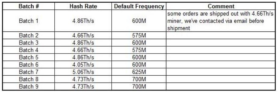
Cheers
wow, this is much more extensive than I was expecting. thanks! I do have a scope and will probably be checking this out at some point.
Sort of too bad that... I imagine you couldn't put a big diode or something with a similar IV curve in its place and route the CLK and D around the dead chip?
As long as your diode can cope with 45+A through it continuously, possibly (assuming you're jumpering out one voltage level). However, I am unsure if you can match the on-load requirements closely enough.
I am unsure if you can jumper using the exposed diagnostic points, my feeling is probably no but would be interesting to try. Removing the chips and soldering jumper wires does not appeal at that scale! Also, I don't have enough hardware to test all of this properly, so some of this is just guesswork. It'd be great if someone who had played with this in real life would confirm some of this stuff. Or if I could get hold of a few more burnt / dead boards!
Interestingly (for me), the LEDs are connected at the end of the chain and seem to be just the busy lines from the last chip.
Take a multimeter and measure the voltage on each heatsink set of 3 (either reference ground or the set of chips prior). You'll usually get one or two sets of "different" voltages. The challenge from there is figuring out what's wrong. If you have a scope, have a look on the power rail to each chip group (VCCIO is hardly ever the issue - it's done from what I recall with a simple resistive dropper). CLKOut from each chip is also a good troubleshooting step - when the chip is working, it passes a regenerated clock out of that port. When it's not hashing due to power issues, you'll see what looks like a sawtooth on that pin (never gets to a good clock, just oscillates at the switching frequency or so)
It's all quite difficult to diagnose as a unit, because generally once one or two chips die in interesting ways, the power performance of the chain in it's entirety is suspect. Even when a chip is just not hashing ("scission of chips" caused by inter-chip comms failures), it can bring the entire chain down or make it unreliable.
You can also follow the reset / busy lines down the board as well as the CI/CO data.
Short version: It's difficult.

wow, this is much more extensive than I was expecting. thanks! I do have a scope and will probably be checking this out at some point.
Sort of too bad that... I imagine you couldn't put a big diode or something with a similar IV curve in its place and route the CLK and D around the dead chip?
Take a multimeter and measure the voltage on each heatsink set of 3 (either reference ground or the set of chips prior). You'll usually get one or two sets of "different" voltages. The challenge from there is figuring out what's wrong. If you have a scope, have a look on the power rail to each chip group (VCCIO is hardly ever the issue - it's done from what I recall with a simple resistive dropper). CLKOut from each chip is also a good troubleshooting step - when the chip is working, it passes a regenerated clock out of that port. When it's not hashing due to power issues, you'll see what looks like a sawtooth on that pin (never gets to a good clock, just oscillates at the switching frequency or so)
It's all quite difficult to diagnose as a unit, because generally once one or two chips die in interesting ways, the power performance of the chain in it's entirety is suspect. Even when a chip is just not hashing ("scission of chips" caused by inter-chip comms failures), it can bring the entire chain down or make it unreliable.
You can also follow the reset / busy lines down the board as well as the CI/CO data.
Short version: It's difficult.
ah. crap. any idea on how to identify bad ones? I guess I could use a thermal camera, but i'd guess that the whole chain never comes up when one is shorted... I imagine maybe they look at the (presumably I2C) bus that all the chips sit on to see which doesn't say 'hi'?